Altivar Drive: 5 Proven Tips for Uptime
For maintenance teams and plant buyers, altivar drive decisions usually begin with a practical question: will the selected part keep the machine running when production pressure is high? Industrial automation relies heavily on human-machine interfaces (HMIs) to ensure seamless communication between machines and operators. The original product context includes XBTE015010, RS232, RS485, PLCHMI, so the goal is not theory alone; it is a dependable replacement or upgrade path for real industrial equipment. A strong altivar drive plan keeps documentation, mounting space, electrical limits, and operator access in view from the start.
Why Altivar Drive Choices Matter
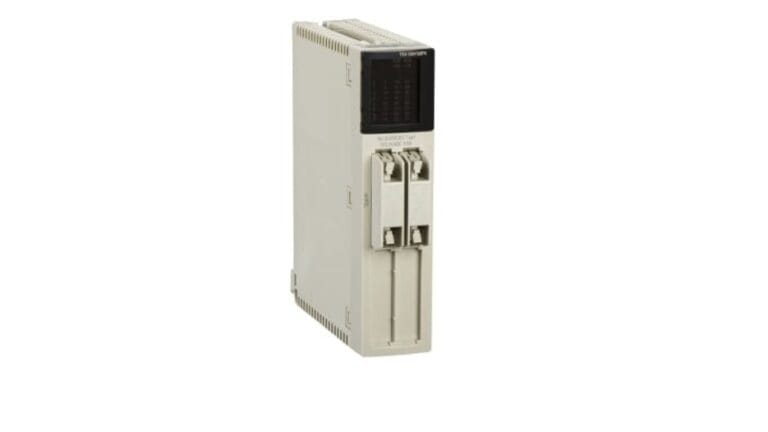
One such reliable device widely used in control panels and factory automation systems is the XBTE015010 MAGELiS Operator. In a busy facility, small mismatches can create long troubleshooting sessions, especially when a controller, panel, communication card, or accessory must fit an existing cabinet. Teams that compare the installed base with the new component reduce commissioning risk and avoid last-minute wiring changes.
1. Confirm the Application Before Ordering
Start by recording the machine role, supply voltage, firmware expectations, mounting style, and connected devices. A altivar drive review should identify whether the part supports visualization, logic control, networking, signal handling, motion, metering, or backup support. This step protects the budget because it catches missing cables, terminal blocks, memory cards, and communication options before the line is stopped.
2. Match the Product Family
Schneider Electric and Modicon systems often depend on family-level compatibility, so a close catalog match is important. Review Schneider Electric automation parts and compare the needed item with nearby products in the same platform. For product browsing, the PLCHMI shop is the safest internal starting point because Siemens, ABB, Red Lion, and mixed-brand replacements should stay in general browsing unless an exact category applies.
3. Check Communication and Integration
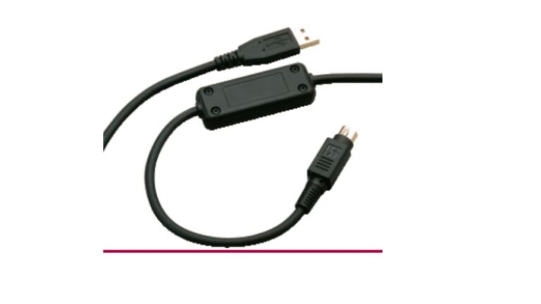
This guide will walk you through the complete process of installation, wiring, configuration, and setup – all explained in simple terms for both beginners and professionals in the automation field. Many failures blamed on hardware are actually integration issues: wrong protocol settings, missing addressing details, unsupported baud rates, or a network module installed without the required configuration. Use a altivar drive checklist that includes controller type, HMI software, fieldbus, memory requirements, and available rack space. For background on human-machine interface, see human-machine interface, then verify final values against the machine documentation.
4. Plan for Harsh Plant Conditions
Industrial sites expose equipment to vibration, heat, dust, humidity, and electrical noise. The right altivar drive selection should account for enclosure rating, terminal condition, grounding, ventilation, and service access. If the part supports operator interaction, readability and ergonomics matter as much as electrical fit; if it supports I/O or networking, signal integrity and cable routing become the priority.
5. Reduce Downtime During Replacement
Understanding the Operator Terminal Before getting into installation, it’s important to understand the function of an operator terminal. Before installing a replacement, back up configuration files, label conductors, photograph existing wiring, and confirm the firmware or application version where possible. A spare that looks correct can still delay recovery if software, licensing, or a small accessory is missing. Keeping the altivar drive process disciplined turns emergency replacement into a controlled maintenance action.
6. Use Trusted Technical References
Reliable automation work depends on more than a part number. Review manufacturer documentation, compare lifecycle status, and use neutral references for general concepts such as human factors. Then connect that knowledge to inventory reality by checking PLCHMI categories like Modicon automation hardware or related control components when they match the system in front of you.
7. Keep Maintenance Simple
A good altivar drive choice should make future service easier. Store the purchase record, configuration notes, compatible accessory list, and any test results with the asset file. It acts as the bridge between the operator and the control system.
This altivar drive check supports reliable startup.
Conclusion
The best altivar drive result combines the original equipment requirement with practical checks for compatibility, environment, communication, and serviceability. When products such as XBTE015010, RS232, RS485, PLCHMI are evaluated this way, teams can protect uptime without overcomplicating the control system. Browse available industrial automation parts to find the right component for your next repair or upgrade.
How do I choose the right altivar drive part?
Confirm the installed part number, electrical rating, firmware needs, and connected devices before ordering. A altivar drive decision is safest when it matches both the product family and the real machine application.
What information should I collect before replacement?
Record the model number, cabinet photos, wiring labels, software version, and any fault messages. This makes comparison faster and reduces the chance of missing a cable, terminal, or accessory.
Can XBTE015010 be replaced without redesigning the system?
In many cases, yes, if the replacement is compatible with the existing platform and configuration. Treat the work as a altivar drive review so communication, mounting, and power requirements are checked before downtime begins.
Where should I look for compatible automation parts?
Start with the exact product family and then compare related PLCHMI categories for HMI, Modicon, communication, I/O, drives, or power meters. Avoid guessing from appearance alone because industrial parts can share a shape while supporting different functions.