Digital Monitoring Instruments: 6 Proven Fixes for Common Faults
In industrial automation and electrical measurement, professionals often struggle to interpret data and keep devices running reliably. When working with units like the PM710MG power meter and associated equipment, it’s essential to understand both how they function and how to resolve issues in real time. Proper troubleshooting of digital monitoring instruments improves uptime, reduces costly downtime, and protects personnel and equipment. This guide covers the most common problems, best practices for diagnosis, and safety measures for resolving faults without unnecessary risk.
Understanding Digital Monitoring Instruments
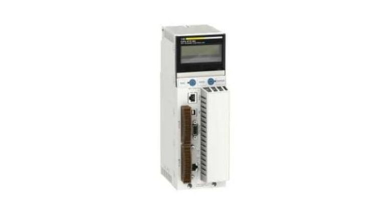
Digital monitoring instruments are devices that measure, record, and communicate electrical parameters in industrial environments. They collect electrical and process data, convert it into readable formats, and often communicate with higher-level systems. Common types include:
- Power measurement meters
- Network communication cards
- Data loggers
- Control interfaces
Accurate readings from these tools are critical for performance monitoring, predictive maintenance, and compliance with safety standards, feeding energy management systems and industrial controllers.
Common Issues in Digital Monitoring Instruments
Problems fall into three categories: hardware errors, communication failures, and software or configuration issues.
1. Power Supply Failures
A frequent root cause is insufficient or unstable power. Check supply voltages, fuses, and connectors; loose connections and degraded cables are common culprits.
2. Internal Component Faults
Sensors, display modules, and internal boards fail over time from stress or age. Visual inspection, self-test diagnostics, and resistance checks help identify these.
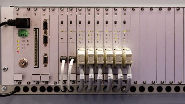
3. Communication Failures Between Devices
Modern systems depend on data exchange, so communication errors are critical. Ensure cables are secure and undamaged, with twisted-pair correctly terminated and shielded in noisy areas. Also verify the Modbus or other protocol settings match the connected system — a protocol mismatch causes data loss or malformed messages.
4. Incorrect Parameter Settings
Measurement ranges, sampling rates, and alarm thresholds must match system requirements. Misconfiguration produces misleading readings or missed alarms.
5. Firmware or Software Bugs
Check regularly for firmware updates and patches. Manufacturers release them to fix known issues, improve performance, and add compatibility.
6. Compatibility of Add-On Modules
When expanding the system, confirm peripheral devices are compatible with the main units. Communication cards augment connectivity and enable seamless data exchange — always verify interface specifications and update drivers to maintain stability.
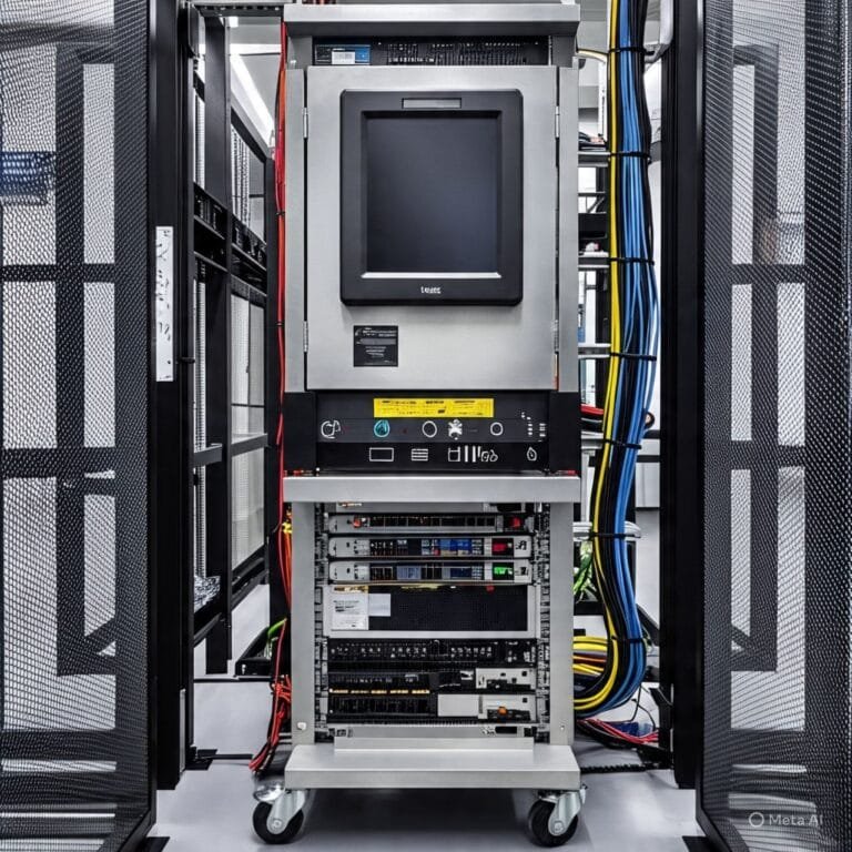
Step-by-Step Troubleshooting Methodology
A structured approach keeps diagnosis consistent and avoids missed details:
- Identify the problem. Define the symptom clearly — no power, inconsistent readings, intermittent communication — using logs and error messages.
- Isolate the cause. Divide the system into power, communication, and software sections, testing each independently with multimeters and protocol analyzers.
- Implement solutions. Replace failing components, correct settings, or update software as needed.
- Verify operation. Run test cycles and confirm expected results under typical load before returning to service.
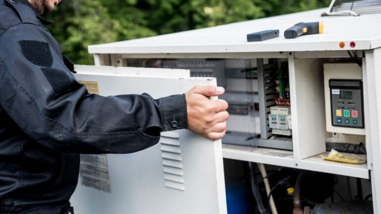
Best Practices for Safe Troubleshooting
Safety is paramount when working with electrical systems:
- Use PPE: Wear gloves, safety glasses, and insulating mats, and follow facility-specific guidelines.
- De-energize when possible: Before opening panels or probing near live components, de-energize whenever safe and feasible, following lockout/tagout procedures.
- Document your work: Record observations, actions, and results to aid future troubleshooting and support audit compliance.
Preventative Maintenance to Avoid Common Issues
Regular maintenance extends instrument life and reduces unexpected failures. Visually inspect devices for wear, corrosion, or impact, and check connectors and seals for environmental protection. Schedule periodic calibration to maintain accuracy and detect drift or degradation before it becomes critical.
Tools and Resources for Troubleshooting
- Diagnostic tools: Multimeters for electrical checks, communication protocol analyzers, and oscilloscopes for signal integrity.
- Documentation and support: Use manuals, wiring diagrams, and reputable support resources, cross-referencing installation guides to confirm correct configuration.
Market Offerings: Products and Competitors
| Model | Functionality | Communication | Typical Usage |
|---|---|---|---|
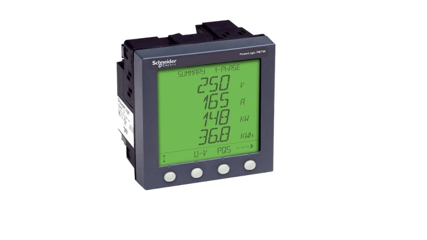
| PM710MG Power Meter | Electrical parameter monitoring | Digital comm ports | Industrial energy measurement |
| Competitor A Multifunction Meter | Energy, voltage, current | Modbus, Ethernet | Facility energy management |
| Competitor B Panel Analyzer | Comprehensive power analysis | RS-485, TCP/IP | Control panel instrumentation |
| Competitor C Compact Logger | Data logging, trending | USB, wireless | Portable diagnostics |
| Competitor D Network Meter | Measurement + network comm | Fieldbus, serial | Distributed monitoring |
Final Thoughts
When expanding your monitoring system or adding modules — such as a 467NHP81100 Profibus DP PCMCIA communication card — confirm peripheral devices are compatible with your main units and update drivers as needed. By following structured troubleshooting, maintaining rigorous safety standards, and understanding both your primary Schneider Electric devices and supporting components, you can resolve issues in digital monitoring instruments effectively and safely. Browse our power meters and monitoring devices to keep your system accurate and reliable.
What are digital monitoring instruments?
They are devices that measure, record, and communicate electrical and process data in industrial settings — power meters, data loggers, communication cards, and control interfaces. They feed energy management systems and controllers with the accurate readings needed for monitoring and maintenance.
What causes inaccurate readings on a power meter?
The most common causes are unstable or insufficient power supply, loose or corroded connectors, incorrect parameter settings (wrong measurement range or sampling rate), sensor drift, and protocol mismatches. Calibration and verifying configuration usually resolve them.
How do I troubleshoot a communication failure between devices?
Start by checking cables and connectors for damage and proper shielding, then confirm both devices use the same communication protocol and settings. Use a protocol analyzer to isolate whether the fault is physical, configuration-related, or a firmware issue.
What safety steps should I take before troubleshooting electrical instruments?
Wear appropriate PPE, follow facility safety rules, and de-energize the system using lockout/tagout whenever it’s safe to open panels or probe near live components. Always document what you do for both safety and audit compliance.