
How to Install and Configure the XBTE015010 MAGELiS Operator Terminal
Industrial automation relies heavily on human-machine interfaces (HMIs) to ensure seamless communication between machines and operators. One such reliable device widely used in control panels and factory automation systems is the XBTE015010 MAGELiS Operator. This guide will walk you through the complete process of installation, wiring, configuration, and setup — all explained in simple terms for both beginners and professionals in the automation field.
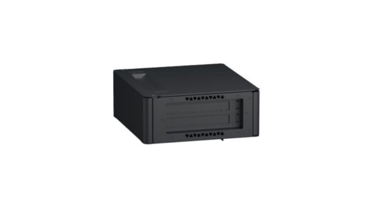
Understanding the Operator Terminal
Before getting into installation, it’s important to understand the function of an operator terminal. It acts as the bridge between the operator and the control system. Through this terminal, users can monitor processes, adjust parameters, and troubleshoot machine operations. The XBTE015010 MAGELiS Operator provides a compact, durable, and user-friendly interface for various industrial environments.
Key features include:
- Graphical display for real-time process visualization
- Functional keypad or touch interface for control input
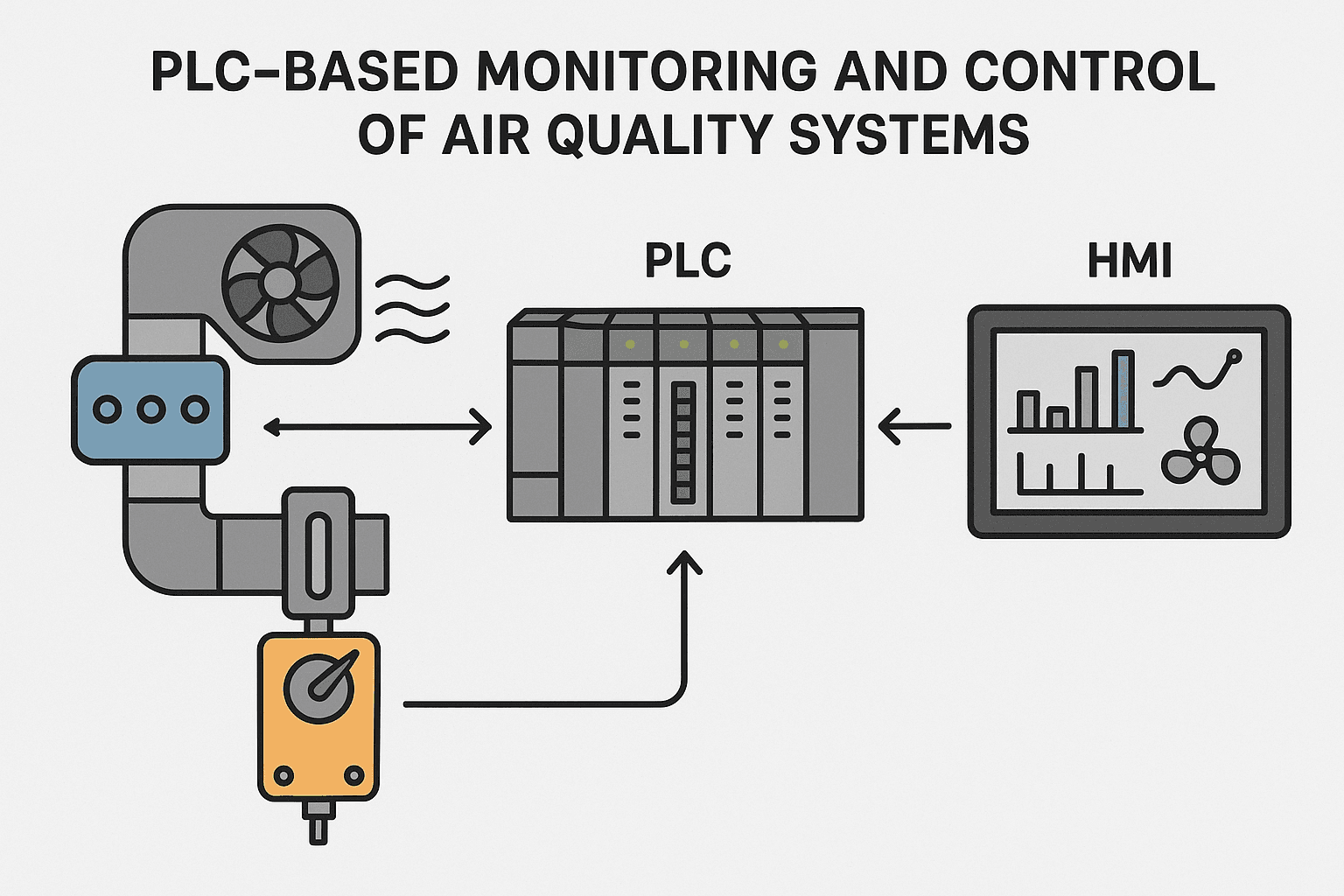
- Compatibility with programmable logic controllers (PLCs)
- Reliable communication protocols for automation systems
Safety and Preparation Before Installation
1. Power Isolation
Before you start, ensure that the main power supply is completely disconnected. Never attempt to wire or install the operator terminal while equipment is live. This prevents the risk of electric shock or hardware damage.
2. Environmental Considerations
Select a clean, dry, and vibration-free area for mounting the terminal. Avoid exposure to extreme temperatures, humidity, or direct sunlight. The enclosure or control panel should provide proper ventilation and protection from dust and moisture.
3. Required Tools and Accessories
Gather the following before installation:
- Screwdrivers (flathead and Phillips)
- Mounting brackets or clips
- Compatible communication cable
- Power supply (according to terminal specifications)
- Configuration software (as per your control system requirement)
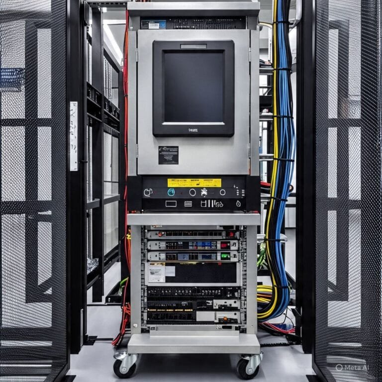
Mounting the Operator Terminal
Proper mounting ensures both safety and longevity of the device. Follow these steps carefully:
Panel Cut-Out
Measure and mark the panel opening according to the dimensions specified in the device’s installation guide. Use a precision cutting tool to create the opening. The edges should be smooth and free from sharp burrs.
Inserting the Terminal
Insert the terminal into the cut-out opening from the front side of the control panel. Make sure it sits evenly against the surface, with no gaps that could allow dust or moisture to enter.
Securing the Device
Use the supplied mounting brackets or fasteners to secure the terminal from the rear side. Tighten screws evenly to avoid stress on the casing. Ensure that the device is firmly fixed but do not over-tighten, as it may damage the housing.
Wiring and Electrical Connections
Power Supply Connection
Connect the DC or AC power input as per the voltage rating indicated in the manual. Use proper terminal lugs and ensure that polarity is correct. An incorrect connection can lead to malfunction or permanent damage.
Grounding
Proper grounding is essential for safety and noise reduction. Connect the ground terminal securely to the control panel grounding point using a suitable conductor.
Communication Interface
Depending on your setup, connect the operator terminal to the PLC or controller using the appropriate communication port — such as RS232, RS485, or Ethernet. Double-check connector orientation and ensure cables are shielded if installed in a noisy industrial environment.
Testing Connections
After all wiring is completed, verify each connection visually and with a multimeter if needed. Only then reconnect the main power supply.
Software Setup and Configuration
Installing Configuration Software
To configure the operator terminal, install the appropriate configuration or programming software on your computer. This software allows you to design screens, assign control buttons, and link communication parameters.
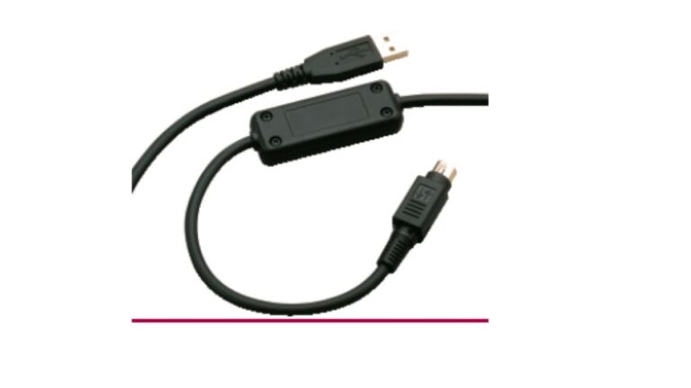
Connecting to the Device
Use the correct cable (USB, serial, or Ethernet) to connect your computer to the terminal. Ensure both devices are powered on and recognized by the system.
Setting Communication Parameters
Configure the communication settings such as baud rate, parity, and stop bits to match those of your PLC or controller. Mismatched parameters will prevent proper data transfer.
Designing the User Interface
Using the configuration software, create operator screens that display essential machine parameters — temperature, pressure, cycle time, alarms, etc. Arrange the buttons and indicators logically for easy operation.
Downloading the Program
Once your configuration is ready, download the project to the terminal. After completion, restart the terminal to apply the settings.
Testing and Verification
After configuration, testing ensures the system performs as expected.
- Power On – Switch on the control panel and verify the terminal display.
- Communication Check – Ensure the device communicates properly with the PLC.
- Function Test – Test all operator keys, indicators, and screen navigation.
- Alarm and Status Verification – Simulate faults or process changes to confirm the alarm indicators function correctly.
If any issues arise, double-check wiring connections and software communication parameters.
Routine Maintenance and Troubleshooting
Proper maintenance extends the life of your operator terminal and minimizes downtime.
1. Regular Cleaning
Dust buildup can reduce visibility and cause overheating. Clean the terminal screen and ventilation areas using a dry, lint-free cloth.
2. Checking Connections
Inspect all terminal blocks and cables periodically. Loose connections can cause intermittent communication failures.
3. Software Updates
Occasionally update your configuration software and firmware to ensure optimal compatibility and performance.
4. Troubleshooting Tips
- If the display does not power up, check the power source and fuse.
- If communication fails, verify COM settings and cable integrity.
- If screen input doesn’t respond, recalibrate or reset the device.
Best Practices for Long-Term Reliability
- Maintain stable power supply and avoid sudden surges.
- Keep a backup of your configuration files.
- Label all cables clearly for easy identification.
- Schedule preventive maintenance every few months.
Final Thoughts
The PLCHMI is a dependable and efficient interface for monitoring and controlling industrial processes. Correct installation, wiring, and configuration ensure reliable performance and minimal downtime. By following the proper steps — from mounting and grounding to programming and testing — you can achieve a safe, user-friendly, and durable control system interface.
Whether you are setting up a new automation line or replacing an older HMI, the PLCHMI provides a practical solution for clear communication between humans and machines. A well-installed and properly configured PLCHMI not only enhances productivity but also improves overall process visibility and safety in any industrial environment.