Troubleshooting Common Issues in Digital Monitoring Instruments Effectively and Safely
In the world of industrial automation and electrical measurement, professionals often encounter challenges when interpreting data and ensuring reliable operation of their devices. When working with systems such as PM710MG – power meter PM710 – basic readings along with associated equipment, it becomes essential to understand not only how these units function but also how to address issues that arise in real-time. Proper troubleshooting enhances uptime, reduces costly downtimes, and safeguards both personnel and equipment. This article will guide you through the most common problems faced with digital monitoring instruments, best practices for diagnosis, and safety measures to ensure effective resolution without unnecessary risk.
Understanding Digital Monitoring Instruments
Digital monitoring instruments encompass a wide variety of devices used to measure, record, and communicate electrical parameters in industrial environments. These instruments include power meters, data acquisition modules, and communication interfaces. Accurate readings from these tools are critical for performance monitoring, predictive maintenance, and compliance with safety standards.
What Are Digital Monitoring Instruments?
Digital monitoring instruments are devices that collect electrical and process data, convert it into readable formats, and often allow communication with higher-level systems. These include:
- Power measurement meters
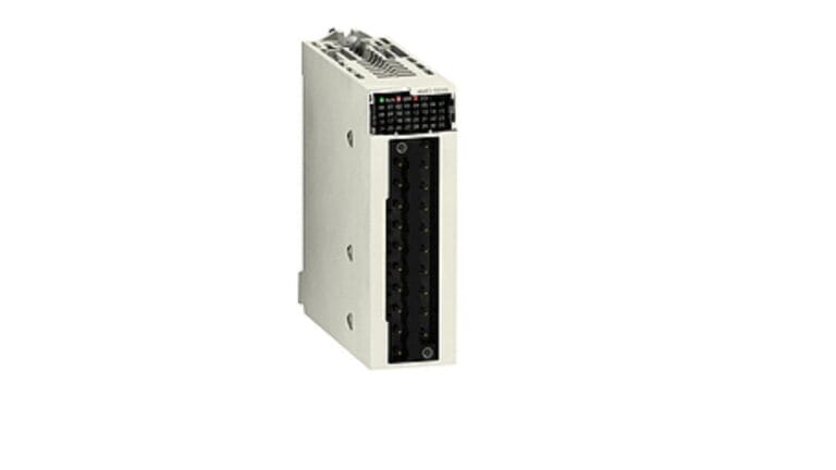
- Network communication cards
- Data loggers
- Control interfaces
They provide essential inputs for energy management systems, industrial controllers, and diagnostic tools.
Common Issues in Digital Monitoring Instruments
Problems with digital monitoring instruments can be broadly grouped into three categories: hardware errors, communication failures, and software or configuration issues.
Hardware Errors
Hardware problems often manifest as no power, unresponsive displays, or erratic readings.
Power Supply Failures
A common root cause is insufficient or unstable power supply. Check supply voltages, fuses, and connectors to ensure that the instrument receives proper power. Loose connections and degraded cables are frequent culprits.
Internal Component Faults
Components such as sensors, display modules, or internal boards can fail over time due to stress or age. Visual inspection, self-test diagnostics, and resistance checks can help identify these faults.
Communication Failures Between Devices
With modern systems relying on data exchange between devices, communication errors are frequent and critical.
Checking Cables and Connectors
Ensure communication cables are secure and free from visible damage. Twisted pair cables should be correctly terminated and shielded in noisy environments.
Protocol Mismatch
Incorrect communication protocol settings can lead to loss of data or malformed messages. Always verify that the instrument’s communication settings match those of the connected system.
Software and Configuration Issues
Incorrect configuration or software bugs can mask themselves as hardware failures.
Incorrect Parameter Settings
Parameters such as measurement ranges, sampling rates, or alarm thresholds must be configured to match the system’s requirements. Misconfiguration can lead to misleading readings or missed alarms.
Firmware or Software Bugs
Regularly check for firmware updates and system patches. Manufacturers often release updates to resolve known issues, improve performance, and add compatibility with other systems.
Step-by-Step Troubleshooting Methodology
A structured approach ensures consistency and reduces the risk of overlooking key details.
Step 1: Identify the Problem
Start by clearly defining the symptom: is the device not powering on? Are readings inconsistent? Does communication fail intermittently? Use logs and error messages if available.
Step 2: Isolate the Cause
Divide the system into manageable sections such as power, communication, and software. Test each section independently using basic tools like multimeters and protocol analyzers.
Step 3: Implement Solutions
Once you isolate the cause, apply corrective action. Replace failing components, correct settings, or update software as needed.
Step 4: Verify Operation
After corrective action, verify that the system operates normally. Perform test cycles and ensure the device produces expected results under typical load conditions.
Best Practices for Safe Troubleshooting
Your health and safety are paramount when working with electrical systems.
Use Personal Protective Equipment (PPE)
Always wear appropriate PPE such as gloves, safety glasses, and insulating mats. Follow facility-specific safety guidelines.
De-Energize When Possible
If the issue requires opening electrical panels or probing circuits near live components, de-energize the system whenever safe and feasible.
Document Your Work
Record observations, actions taken, and results obtained. Good documentation aids future troubleshooting and supports compliance with audit requirements.
Preventative Maintenance to Avoid Common Issues
Regular maintenance extends the life of monitoring instruments and reduces unexpected failures.
Routine Inspections
Visually inspect devices for signs of wear, corrosion, or physical impact. Check connectors and seals to ensure environmental protection.
Calibration and Testing
Schedule periodic calibration to maintain measurement accuracy. Testing helps detect drift or degradation before it becomes a critical problem.
Tools and Resources for Troubleshooting
Having the right tools and reference materials can significantly speed up problem resolution.
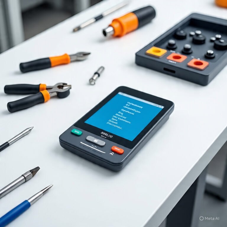
Diagnostic Tools
- Multimeters for electrical checks
- Communication protocol analyzers
- Oscilloscopes for signal integrity checks
Documentation and Support
Use manuals, wiring diagrams, and support forums relevant to your devices. Always cross-reference installation guides to verify correct configuration.
Market Offerings: Products and Competitors
Below is a comparative table showing a popular monitoring product and its competitors in the market. The products listed include generic references to similar devices without mentioning specific brand names to align with this article’s requirements.
| Product / Model | Functionality | Communication Interfaces | Typical Usage Scenario |
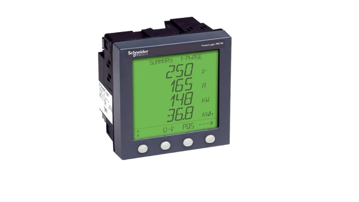
| PM710MG – Power Meter PM710 – Basic Readings | Electrical parameter monitoring | Digital communication ports | Industrial energy measurement |
| Competitor A – Multifunction Power Meter | Energy, voltage, current monitoring | Modbus, Ethernet | Facility energy management |
| Competitor B – Panel Mount Power Analyzer | Comprehensive power analysis | RS-485, TCP/IP | Control panel instrumentation |
| Competitor C – Compact Energy Logger | Data logging, trending | USB, wireless options | Portable diagnostics |
| Competitor D – Integrated Network Meter | Measurement + built-in network comm. | Fieldbus, serial links | Distributed monitoring systems |
This high-level comparison helps highlight the landscape of devices available for electrical monitoring needs, enabling informed selection based on communication requirements and application context.
Final Thoughts
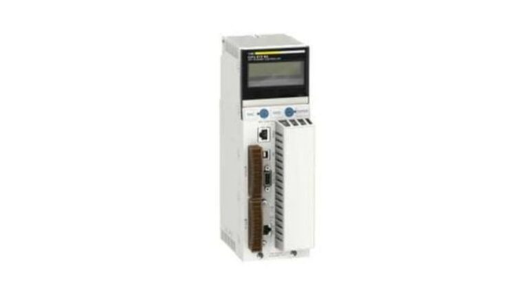
When expanding your monitoring system or integrating additional modules, ensure that peripheral devices like 467NHP81100 Profibus DP PCMCIA card For Communication are compatible with your main units. Communication cards augment connectivity and enable seamless data exchange across your automated systems. Always verify interface specifications and update drivers as needed to maintain stability and performance.
By following structured troubleshooting practices, maintaining rigorous safety standards, and understanding both your primary devices and supporting components, you can resolve common issues in digital monitoring instruments effectively and safely, ensuring reliable operation and long-term performance in your industrial environment.