Common FANUC alarm Codes are critical alerts in CNC machinery, signaling issues that require immediate attention.

Break Free from Frustration: FANUC Alarm Codes Demystified

Introduction to FANUC Alarms

Common FANUC alarm Codes are critical alerts in CNC machinery, signaling issues that require immediate attention. Properly understanding and addressing these alarms is essential to maintaining optimal machine performance and avoiding costly downtime.

Categories of FANUC Alarms

1. System Alarms

System alarms indicate issues with the CNC system itself. These could range from memory problems to system initialization failures.

2. Servo Alarms

Servo alarms point to issues within the servo drive or motor, such as overloading, overheating, or communication errors.

3. Spindle Alarms

Spindle alarms are related to the spindle drive or motor, indicating problems like over-speed, over-current, or cooling failures.

4. Overtravel Alarms

Overtravel alarms occur when the machine exceeds its defined travel limits, potentially causing mechanical damage.

Common FANUC Alarms Codes and Their Solutions

System Alarms

  • Alarm 900: RAM Parity Error
    • Cause: Memory corruption or failure.
    • Solution: Check memory modules and replace if necessary.
  • Alarm 1000: Overheat
    • Cause: Excessive heat in the control cabinet.
    • Solution: Improve ventilation or check cooling systems.

Servo Alarms

  • Alarm 300: Overload
    • Cause: Servo motor is drawing too much current.
    • Solution: Check for mechanical binding or excessive load on the motor.
  • Alarm 310: Overheat
    • Cause: Servo motor is overheating.
    • Solution: Ensure proper cooling and check ambient temperature.

Spindle Alarms

  • Alarm 2000: Over-speed
    • Cause: Spindle speed exceeds the set limit.
    • Solution: Check speed settings and reduce spindle load.
  • Alarm 2010: Over-current
    • Cause: Excessive current draw by the spindle motor.
    • Solution: Inspect spindle drive and motor for faults.

Overtravel Alarms

  • Alarm 500: Overtravel
    • Cause: Axis movement exceeds the defined limit.
    • Solution: Adjust travel limits and check for obstructions.

Preventive Measures for FANUC Alarm

  1. Regular Maintenance
    • Routine checks and maintenance of CNC machinery can prevent many common alarms.
  2. Proper Training
    • Ensure operators are well-trained to understand and respond to alarms promptly.
  3. Environmental Control
    • Maintain a clean and controlled environment to prevent overheating and dust accumulation.
  4. Software Updates
    • Keep the CNC control software updated to benefit from the latest improvements and fixes.

Advanced Troubleshooting Techniques

  1. Diagnostic Tools
    • Utilize FANUC’s diagnostic tools to pinpoint and resolve issues accurately.
  2. Manufacturer Support
    • Reach out to FANUC support for complex problems that require expert assistance.
  3. Documentation
    • Always refer to the official FANUC manuals for detailed troubleshooting steps.
Common FANUC alarm Codes are critical alerts in CNC machinery, signaling issues that require immediate attention.

Case Study: Resolving a FANUC Overtravel Alarm

Problem

A manufacturing plant experienced frequent overtravel alarms on their CNC machines, causing significant downtime.

Solution

  1. Initial Assessment
    • The maintenance team first reviewed the machine’s travel limits and adjusted them appropriately.
  2. Mechanical Inspection
    • They inspected the mechanical components for any obstructions or misalignments.
  3. Software Check
    • The team updated the CNC control software to the latest version to ensure no software-related issues.
  4. Operator Training
    • Operators were re-trained to recognize early signs of potential overtravel and take preventive actions.

Outcome

These steps significantly reduced the occurrence of overtravel alarms, leading to improved machine uptime and productivity.

Future Trends in CNC Machine

  1. Predictive Maintenance
    • Leveraging IoT and AI to predict and prevent potential alarm conditions before they occur.
  2. Enhanced Diagnostics
    • Advanced diagnostic tools and software will provide more detailed insights into alarm causes and solutions.
  3. Remote Monitoring
    • Remote monitoring solutions will allow for real-time tracking and troubleshooting of alarms from anywhere.

Conclusion

Understanding and effectively managing FANUC alarms is crucial for maintaining the efficiency and productivity of CNC machinery. By implementing preventive measures, utilizing advanced troubleshooting techniques, and staying updated with the latest trends, manufacturers can minimize downtime and ensure smooth operations. To have more informtaion regarding the common FANUC alarm codes, visit our website or call us at +1 416 840 4997 or info@plchmi.shop

FAQs (FANUC Alarm)

1. What is a FANUC alarm?

A FANUC alarm is an alert generated by FANUC CNC machinery to indicate a problem that needs attention, ranging from system errors to hardware malfunctions.

2. How can I troubleshoot a FANUC servo alarm?

To troubleshoot a FANUC servo alarm, check for mechanical binding, ensure proper cooling, and inspect the servo drive and motor for faults.

3. What causes a Common FANUC Alarms Codes spindle alarm?

A FANUC spindle alarm can be caused by issues such as over-speed, over-current, or cooling failures in the spindle drive or motor.

4. How can I prevent Common FANUC Alarms Codes overtravel?

Prevent FANUC overtravel alarms by regularly adjusting travel limits, checking for obstructions, and ensuring operators are well-trained to recognize early warning signs.

5. What are the benefits of predictive maintenance in CNC machinery?

Predictive maintenance helps prevent potential alarm conditions, reduces downtime, and improves overall machine reliability by leveraging IoT and AI technologies.

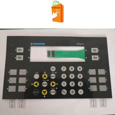
Schneider Electric's Magelis XBTPM027010 combines advanced touchscreen technology with robust connectivity options to streamline industrial control and monitoring tasks.

Magelis HMIs: Key Insights, Solutions, and Comprehensive FAQs

Magelis Human Machine Interfaces (HMIs) by Schneider Electric are widely used in industrial automation for their reliable performance and advanced features. Below, we address some common issues and provide solutions to ensure your HMIs function optimally. Allow to discuss the key insights and solutions of Magelis HMIs

Common Issues and Solutions

1. Incorrect Floating Point Value Readings

One common problem with Magelis HMIs is the incorrect display of floating-point values on alphanumeric displays. This issue arises when using the %MW register instead of the %MF register. The %MW register is designed for integers, not floating points, causing display errors. To correct this, always use the %MF register for floating-point values to ensure accurate readings.

2. Connecting External Speakers

For users needing to connect external speakers to the HMIPUC9D0E01 Panel PC, it includes a line-out port specifically for this purpose. This allows for easy integration of audio components to enhance the functionality of the HMI system.

3. Alarm Log Preservation

A critical feature of any HMI system is the ability to maintain alarm logs even during power outages or system reboots. In Magelis HMIs, enabling the “Backup Alarm Group” property ensures that alarm buffers are saved in both DRAM and SRAM. This dual storage method provides redundancy, ensuring that alarm history is retained. Additionally, utilizing the “Save To File” option allows alarm data to be exported to Excel, providing a comprehensive history for analysis and compliance purposes.

4. RS-485 Cable for M221 to XBTN401 Connection

Connecting an M221 PLC to an XBTN401 HMI using an RS-485 cable requires a custom wiring configuration. The specific pinouts needed are:

  • Pin 4 to Pin 4
  • Pin 5 to Pin 5
  • Pin 7 to Pin 7
  • Pin 8 to Pin 8

This custom cable ensures reliable communication between the PLC and HMI.

5. PLC Returned Error Code 02H

Receiving an error code 02H typically indicates that the HMI is attempting to access an undefined or inaccessible address within the slave device. To resolve this issue, double-check the communication settings and register mappings to ensure that the HMI and PLC are correctly configured for communication.

6. Candela per Square Meter for HMIs

The brightness of HMI screens, measured in candela per square meter (cd/m²), varies across different models. For the HMIGTO series, the candela values range from 350 to 500 cd/m², depending on the screen size. This measurement is crucial for ensuring visibility in various lighting conditions.

7. Communication with M241 via SoMachine Protocol

To successfully establish communication between a Magelis HMI and an M241 PLC using the SoMachine protocol, it is essential to adjust the default communication settings. This involves setting the correct baud rate and parity to match the requirements of the M241, facilitating seamless data exchange.

8. Mounting Angle for HMIPPF7A2701

The HMIPPF7A2701 HMI can be mounted at a 45-degree angle provided the ambient temperature does not exceed 85°F and there is adequate airflow. This flexibility in mounting options ensures that the HMI can be installed in various positions to suit different operational requirements.

9. Password Change Prompts

In Vijeo Designer, Password Management is a critical security feature. Users may be prompted to change their passwords at first login or periodically thereafter. This practice enhances security by ensuring that access credentials are regularly updated.

10. Data Logging Issues

Vijeo Designer optimizes data logging by recording only changes in variable values, rather than continuous logging. To ensure email functionality via SMTP, it is crucial to verify network settings and ensure that the HMI is properly configured for email communication.

11. TM2 Module Compatibility

Magelis STU and STO series HMIs are incompatible with TM2 expansion modules. Instead, the HMISCU series should be used for applications requiring TM2 modules. This compatibility issue highlights the importance of selecting the correct HMI model for your specific application needs.

12. Pressure Resistance

The HMIGTO xx15 series of HMIs are designed to withstand pressures up to 145 psi. This durability makes them suitable for use in harsh industrial environments where equipment may be exposed to high pressure.

Magelis HMI Maintenance Tips

Maintaining your Magelis HMI is crucial for ensuring long-term reliability and performance. Here are some additional tips:

  • Regular Firmware Updates: Ensure that your HMI firmware is always up to date to benefit from the latest features and security patches.
  • Backup Configurations: Regularly back up your HMI configurations to prevent data loss in case of hardware failure.
  • Clean Display Screens: Keep the HMI screens clean to maintain visibility and touch sensitivity. Use appropriate cleaning agents recommended by the manufacturer.
  • Monitor Environmental Conditions: Ensure that the HMI operates within the recommended temperature and humidity ranges to prevent damage.

Contact Information

For more information or assistance with Magelis HMIs, please contact:

  • Phone: +1 416 840 4997
  • Email: sales@plchmi.shop
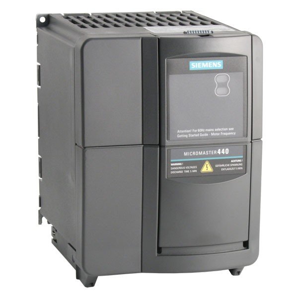
Siemens Micromaster 440

Understanding Siemens Micromaster 440 Fault Codes

Introduction

The Siemens Micromaster 440 is a versatile and powerful variable frequency drive (VFD) widely used in industrial applications for motor control. Like any sophisticated piece of equipment, it can encounter various faults that need to be diagnosed and resolved to maintain optimal operation. This article delves into the common fault codes of the Siemens Micromaster 440, their meanings, causes, and troubleshooting steps. We have been serving the automation and control industry for years, providing top-notch solutions to clients around the globe. Our commitment to excellence and customer satisfaction is unwavering, and we are proud to be available 24/7 to meet your needs. Whether you require expert consultation, cutting-edge products, or reliable support, we are here to assist you anytime, anywhere.

Introduction to Siemens Micromaster 440

The Siemens Micromaster 440 is designed for complex and high-performance motor control applications. It offers advanced features such as vector control, numerous programmable I/O, and extensive communication options. Despite its robust design, users may occasionally encounter fault codes indicating issues that need addressing.

Common Siemens Micromaster 440 Fault Codes

Here, we cover some of the most frequently encountered fault codes, providing detailed explanations and solutions.

F0001: Overcurrent

Meaning: The drive has detected an overcurrent condition.

Causes:

  • Short circuit or ground fault
  • Motor stall
  • Incorrect motor parameters
  • Rapid acceleration/deceleration

Troubleshooting:

  • Check the motor and cable for short circuits.
  • Verify the motor parameters and match them with the motor nameplate.
  • Adjust the acceleration and deceleration times.
  • Ensure proper load settings and motor conditions.

F0002: Overvoltage

Meaning: The DC link voltage has exceeded the permissible limit.

Causes:

  • Excessive line voltage
  • Insufficient braking resistor
  • High regenerative energy from the motor

Troubleshooting:

  • Check the line voltage and compare it with the drive’s specifications.
  • Install or check the braking resistor.
  • Adjust the deceleration ramp to reduce regenerative energy.

F0003: Undervoltage

Meaning: The DC link voltage is below the permissible limit.

Causes:

  • Low line voltage
  • Power supply issues

Troubleshooting:

  • Verify the line voltage is within the specified range.
  • Inspect the power supply connections and components.

F0004: Inverter Overtemperature

Meaning: The inverter’s internal temperature has exceeded the safe operating limit.

Causes:

  • Inadequate cooling
  • High ambient temperature
  • Clogged air filters

Troubleshooting:

  • Ensure adequate ventilation and cooling for the drive.
  • Check the ambient temperature and maintain it within the specified limits.
  • Clean or replace air filters as necessary.

F0005: Motor Overtemperature

Meaning: The motor temperature has exceeded the permissible limit.

Causes:

  • Overloaded motor
  • Insufficient cooling
  • Incorrect motor settings

Troubleshooting:

  • Reduce the motor load to within safe operating levels.
  • Ensure proper motor cooling and ventilation.
  • Verify and correct the motor parameters.

F0011: Motor Stall

Meaning: The motor has stalled during operation.

Causes:

  • Excessive load
  • Mechanical blockage
  • Incorrect motor parameters

Troubleshooting:

  • Reduce the load on the motor.
  • Check for mechanical blockages or obstructions.
  • Adjust the motor parameters to match the application requirements.

F0012: External Fault

Meaning: An external fault has been triggered.

Causes:

  • Faulty external wiring or devices
  • Incorrect parameter settings

Troubleshooting:

  • Inspect and correct external wiring and connections.
  • Verify external devices are functioning correctly.
  • Adjust the relevant parameters to ensure proper operation.

F0025: Parameter Error

Meaning: There is an error in one or more parameters.

Causes:

  • Incorrect parameter settings
  • Corrupted parameter file

Troubleshooting:

  • Review and correct the parameter settings.
  • Reset to factory settings if necessary and reconfigure the parameters.

Preventive Measures and Maintenance Tips

To minimize the occurrence of fault codes and ensure smooth operation of the Siemens Micromaster 440, consider the following preventive measures and maintenance tips:

  • Regular Inspections: Periodically inspect the drive, motor, and associated components for wear and damage.
  • Proper Ventilation: Ensure that the drive is installed in a well-ventilated area to prevent overheating.
  • Parameter Verification: Regularly verify and update parameter settings to match the application requirements.
  • Routine Cleaning: Keep the drive and surrounding area clean and free of dust and debris.
  • Firmware Updates: Keep the drive’s firmware updated to benefit from the latest features and fixes.

Conclusion

Understanding and troubleshooting Siemens Micromaster 440 fault codes is crucial for maintaining the efficiency and reliability of your motor control system. By familiarizing yourself with the common fault codes and their resolutions, you can quickly diagnose issues and implement corrective actions, minimizing downtime and enhancing productivity.

For more detailed information, technical support, or to purchase Siemens Micromaster 440 drives and accessories, visit our website or contact us directly at +1 416 840 4997 or sales@plchmi.shop.

The Modicon 984 Family of PLCs

The Modicon 984 family of PLCs brings high performance, application flexibility, and programming compatibility to the small controller market. As a member of the 984 family, the Compact Controllers implement a common instruction set for developing user logic, standard Modbus communication functionality, and optional Modbus Plus communication capabilities.

Key Features of Modicon 984 Compact Controllers

The Compact Controllers share the following 984 processing architecture features:

  • Memory Section: Stores user logic, state RAM, and system overhead in battery-backed CMOS RAM. The system’s Executive firmware is held in nonvolatile PROM or FLASH RAM.
  • CPU Section: Solves the user logic program based on current input values in state RAM, then updates the output values in state RAM.
  • I/O Processing Section: Directs the flow of signals from input modules to state RAM and provides a path over which output signals from the CPU’s logic solve are sent to the output modules.
  • Communications Section: Provides one or more port interfaces, allowing the controller to communicate with programming panels, host computers, hand-held diagnostic tools, and other master devices, as well as with additional controllers and other nodes on a Modbus or Modbus Plus network.

Architectural Consistency and Compatibility

This architectural consistency allows the Modicon 984 family of PLCs to achieve machine compatibility with other controllers in the family. Sequences of user logic created on a mid-range or high-performance controller, such as a 984B or a 984-685 Controller, can be easily relocated to a Compact. Furthermore, user logic generated for this small controller is upwardly compatible with larger 984 controllers, ensuring seamless integration into a multi-controller network.

Benefits of Choosing Modicon 984 Compact Controllers

Choosing Modicon 984 Compact Controllers offers several benefits:

  • High Performance: Compact yet powerful, these controllers meet the demands of complex applications.
  • Flexibility: Easily adaptable to various application needs and scalable across different controller sizes.
  • Ease of Integration: Compatible with existing systems, ensuring minimal disruption during upgrades or expansions.
  • Enhanced Communication: Supports standard Modbus and optional Modbus Plus, facilitating robust and reliable communication networks.

Why Modicon 984 Family?

The Modicon 984 family is renowned for its reliability and efficiency in industrial automation. The Compact Controllers are ideal for users seeking a balance of performance and cost-effectiveness in a small form factor. Their ability to seamlessly integrate with other controllers in the family makes them a versatile choice for expanding and upgrading automation systems.

Contact Us

For more detailed information on Modicon 984 Compact Controllers and how they can benefit your automation needs, please visit our website, call us at +1-416-840-4997, or email us at sales@plchmi.shp. Our team is ready to assist you with any queries and provide you with the best solutions tailored to your requirements.

By focusing on these features and benefits, you can ensure that your industrial automation systems are efficient, reliable, and future-proof with the Modicon 984 family of PLCs.

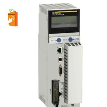
he 140CPU65860 module is installed in a Modicon Quantum PLC rack. It is configured using Schneider Electric’s programming software,

History of Modicon PLC

Richard E. Morley, affectionately known as Dick, was a pioneering American electrical engineer whose groundbreaking work revolutionized industrial automation. While working at Bedford and Associates in Massachusetts, Morley spearheaded the development of the first Programmable Logic Controller (PLC) for General Motors and the Modicon brand in 1968. General Motors (GM), headquartered in Detroit, Michigan, is a leading American multinational corporation renowned for engineering, manufacturing, marketing, and distributing vehicles and vehicle parts, as well as providing financial services.

Morley’s contributions extend far beyond his engineering feats. As an esteemed author, educator, and influencer, his achievements have earned him numerous accolades from prestigious organizations including ISA (the Instrumentation Systems and Automation Society), Inc. Magazine, Franklin Institute, SME (the Society of Manufacturing Engineers), and the Engineering Society of Detroit. In honor of his legacy, SME presents the Richard E. Morley Outstanding Young Manufacturing Engineer Award, recognizing exceptional technical accomplishments in manufacturing by engineers aged 35 and under.

Today, Schneider Electric proudly owns the Modicon brand of PLCs. These devices represent a monumental advancement in the automation industry, transforming manufacturing processes globally. Designed to replace the arduous and expensive process of re-wiring and hard-wired control panels, PLCs enable software program changes to streamline production updates. Before the advent of PLCs, manufacturing relied on multiple relays, drum sequencers, cam timers, and closed-loop controllers, necessitating extensive and costly re-wiring. The Modicon 084 PLC, the first of its kind, was programmed in ‘ladder logic,’ mirroring the schematic diagrams of the relay logic it supplanted, thus facilitating a smoother transition for engineers and manufacturing professionals. The automotive industry remains a predominant user of PLCs. PLCHMI offers new and refurbished Modicon parts, including the Modicon Quantum series, along with repair services. For more information, please call +1 416 840 4997 or email sales@plchmi.shop.

Modicon PLC History

The Modicon PLC Timeline

In the early 1970s, PLC communication took a significant leap forward with the introduction of Modbus, the first industrial communications network. Based on a Slave/Master architecture, Modbus utilized messaging to enable communication between Modbus nodes, though initial lack of standardization posed challenges for PLC communications.

During the 1980s, General Electric introduced the Manufacturing Automation Protocol (MAP) to standardize the interconnection of devices from various manufacturers. Concurrently, PLC programming software evolved to operate on both personal and professional computers, eliminating the need for dedicated programming terminals or handheld programmers.

As technology has progressed, so have PLCs. Modern PLCs now encompass process, motion, and distributed control systems, as well as sophisticated networking capabilities. They offer data handling, storage capacities, and processing power equivalent to that of standard desktop computers, making them indispensable in today’s manufacturing landscape.

PLCs have continually adapted to meet the demands of an ever-evolving industrial environment. Their ability to streamline processes, enhance efficiency, and reduce costs has cemented their role as a cornerstone of modern manufacturing. From automotive production lines to complex industrial systems, PLCs remain a critical component in achieving operational excellence.

PLC - Industrial automation

PLC Data Logging and Custom PLC Solutions

Introduction

Programmable Logic Controllers (PLCs) are essential components in industrial automation, providing robust control and monitoring solutions across various applications. This article explores three critical aspects of PLCs: data logging, custom PLC solutions and PLCs for bigineers.

What is a PLC?

A Programmable Logic Controller (PLC) is a specialized computer used to control machinery and processes in industrial environments. It is designed to handle complex control tasks with high reliability and flexibility. PLCs are integral to manufacturing lines, energy management systems, and other industrial applications where precise control and monitoring are necessary.

History and Evolution of PLCs

PLCs were first developed in the late 1960s to replace relay-based control systems. The first PLC, the Modicon 084, was introduced in 1968 and revolutionized industrial automation by offering programmable and flexible control systems. Over the years, PLCs have evolved to include advanced features such as real-time processing, enhanced communication capabilities, and integration with other industrial systems like SCADA and MES.

PLC for Beginners

Understanding the Basics

For beginners, understanding the fundamentals of PLCs is crucial. A PLC consists of a central processing unit (CPU), input/output (I/O) modules, power supply, and communication interfaces. The CPU executes control instructions stored in its memory, while I/O modules interface with sensors and actuators to monitor and control processes.

Key Components of a PLC

  1. Central Processing Unit (CPU): The brain of the PLC, responsible for executing control logic.
  2. Input/Output (I/O) Modules: Interface with external devices such as sensors (inputs) and actuators (outputs).
  3. Power Supply: Provides the necessary power to the PLC and its components.
  4. Communication Interfaces: Enable the PLC to communicate with other devices and systems.

Basic Programming Concepts

PLCs are typically programmed using ladder logic, a graphical programming language resembling electrical relay logic diagrams. Other programming languages include Function Block Diagram (FBD), Structured Text (ST), and Sequential Function Chart (SFC). Beginners should start with ladder logic due to its simplicity and ease of understanding.

Getting Started with PLC Programming

  1. Choose a PLC Brand: Popular brands include Siemens, Allen-Bradley, and Schneider Electric.
  2. Select a Programming Software: Each brand has its own software, such as Siemens’ TIA Portal or Allen-Bradley’s RSLogix.
  3. Learn Basic Instructions: Start with simple instructions like contacts, coils, and timers.
  4. Create Simple Programs: Write basic programs to control simple processes, such as turning a light on and off.
  5. Test and Debug: Use simulation tools provided by the programming software to test and debug your programs.

Practical Applications for Beginners

Beginners can start with simple applications to gain hands-on experience. Examples include:

  • Traffic Light Control: Simulate the control of traffic lights at an intersection.
  • Conveyor Belt System: Control the movement of a conveyor belt based on sensor inputs.
  • Temperature Control: Use a temperature sensor to control a heating element.

PLC Data Logging

Importance of Data Logging

Data logging is the process of collecting and storing data over time for analysis and monitoring purposes. In industrial automation, data logging is crucial for:

  • Process Optimization: Analyzing data to identify inefficiencies and optimize processes.
  • Predictive Maintenance: Monitoring equipment performance to predict and prevent failures.
  • Compliance and Reporting: Ensuring processes comply with regulatory standards and generating reports for audits.

How PLC Data Logging Works

PLC data logging involves capturing data from sensors, actuators, and other devices connected to the PLC. The data is then stored in memory or transmitted to external storage devices or systems for further analysis. Key components of a data logging system include:

  • Sensors and Actuators: Collect real-time data from the process.
  • PLC Memory: Temporarily stores the data before it is transmitted.
  • Communication Interfaces: Transmit data to external storage or analysis systems.
  • Data Storage: External databases or cloud storage systems that hold the logged data.

Setting Up PLC Data Logging

  1. Define Data Points: Identify the specific data points you need to log (e.g., temperature, pressure, flow rate).
  2. Configure I/O Modules: Set up the I/O modules to collect data from the sensors and actuators.
  3. Program Data Logging Instructions: Write PLC programs to read and store the data points at specified intervals.
  4. Set Up Communication: Configure communication interfaces to transmit data to external storage or monitoring systems.
  5. Implement Data Storage: Use databases, cloud storage, or local storage systems to save the logged data.

Applications of PLC Data Logging

PLC data logging is widely used in various industries, including:

  • Manufacturing: Monitoring production processes and equipment performance.
  • Energy Management: Tracking energy consumption and optimizing energy use.
  • Water Treatment: Monitoring water quality parameters and controlling treatment processes.
  • HVAC Systems: Logging temperature, humidity, and airflow data for climate control.

Challenges and Solutions in PLC Data Logging

  1. Data Volume: Large volumes of data can overwhelm storage systems. Solution: Use data compression and efficient storage techniques.
  2. Data Accuracy: Ensuring data accuracy and reliability is critical. Solution: Implement calibration and validation procedures.
  3. Real-Time Processing: Real-time data processing can be challenging. Solution: Use high-performance PLCs and optimized programming techniques.
  4. Integration: Integrating data logging systems with other industrial systems can be complex. Solution: Use standardized communication protocols and middleware.

Custom PLC Solutions

Benefits of Custom PLC Solutions

Custom PLC solutions are tailored to meet the specific needs of an application or process. Benefits include:

  • Flexibility: Custom solutions can be designed to fit unique requirements and constraints.
  • Scalability: Custom PLCs can be scaled up or down based on the application’s needs.
  • Efficiency: Optimized for specific tasks, custom solutions can improve efficiency and performance.
  • Cost-Effectiveness: By focusing on necessary features, custom solutions can reduce costs.

Designing Custom PLC Solutions

  1. Requirement Analysis: Identify the specific requirements and constraints of the application.
  2. System Design: Develop a detailed design that includes hardware, software, and communication components.
  3. Component Selection: Choose the appropriate PLC, I/O modules, and other components.
  4. Programming: Write custom programs tailored to the application’s requirements.
  5. Testing and Validation: Test the system thoroughly to ensure it meets the design specifications.

Examples of Custom PLC Solutions

  1. Automated Assembly Line: A custom PLC solution designed to control and monitor an automated assembly line, ensuring precise coordination between robots, conveyors, and other equipment.
  2. Energy Management System: A tailored PLC solution for monitoring and optimizing energy use in a manufacturing facility, integrating with renewable energy sources and energy storage systems.
  3. Water Treatment Plant: Custom PLCs designed to control and monitor the various stages of water treatment, ensuring compliance with regulatory standards and optimizing treatment processes.

Implementing Custom PLC Solutions

  1. Project Planning: Develop a detailed project plan that outlines the steps and timeline for implementation.
  2. System Integration: Integrate the custom PLC solution with existing systems and infrastructure.
  3. Training and Support: Provide training for operators and maintenance personnel, and offer ongoing support to ensure smooth operation.
  4. Monitoring and Optimization: Continuously monitor the system’s performance and make necessary adjustments to optimize efficiency and effectiveness.

Conclusion

Programmable Logic Controllers (PLCs) are indispensable in modern industrial automation, offering robust control, monitoring, and data logging capabilities. For beginners, understanding the basics of PLCs and getting started with simple programming tasks is crucial. PLC data logging plays a vital role in process optimization, predictive maintenance, and regulatory compliance, while custom PLC solutions provide tailored, efficient, and cost-effective automation systems. By leveraging these aspects, industries can enhance productivity, efficiency, and reliability, ensuring continued success in an increasingly automated world. We are PLCHMI, provide all type of support services for PLCs and HMIs around the word.

FAQs

What is a PLC?

A Programmable Logic Controller (PLC) is a specialized computer used to control and monitor industrial processes and machinery.

How does PLC data logging benefit industries?

PLC data logging helps optimize processes, predict maintenance needs, and ensure compliance with regulatory standards.

What are custom PLC solutions?

Custom PLC solutions are tailored automation systems designed to meet the specific needs of an application or process.

How can beginners start with PLC programming?

Beginners can start with ladder logic programming, using simple instructions and creating basic programs to control simple processes.

Why are PLCs important in industrial automation?

PLCs provide reliable and flexible control and monitoring solutions, essential for efficient and effective industrial automation. PLCHMI.shop is a reliable place to buy SE controllers.

PLC - Industrial automation

Industrial Automation with PLCs

Introduction

In the realm of industrial automation, Programmable Logic Controllers (PLCs) stand as the backbone of modern manufacturing processes. These versatile devices have revolutionized the way industries operate, bringing efficiency, flexibility, enhanced industrial automation and reliability to the forefront. In this article, we will explore how PLCs contribute to making significant improvements in industrial automation. This is an excellent tool for enhancing industrial automation.

  1. Flexibility and Adaptability

One of the key advantages of PLCs is their ability to adapt to changing manufacturing requirements. Traditional control systems often involve complex and rigid wiring, making modifications a time-consuming and costly endeavor. PLCs, on the other hand, offer a high degree of flexibility. Their programmable nature allows for swift alterations in control logic, facilitating quick adjustments to accommodate changes in production processes or product specifications.

For instance, in a manufacturing setup where product variations are common, PLCs can easily handle different parameters and sequences by simply reprogramming the controller. This adaptability reduces downtime associated with reconfiguration, enabling industries to respond promptly to market demands and changes in production requirements.

  1. Enhanced Control and Precision

PLCs excel in providing precise control over industrial processes. Their ability to execute complex sequences of operations with high accuracy ensures consistent product quality. PLCs can monitor and control variables such as temperature, pressure, and flow rates with remarkable precision, leading to improved production efficiency and reduced waste.

In scenarios where tight control is critical, such as in chemical manufacturing or food processing, PLCs play a pivotal role in maintaining optimal conditions. This level of precision enhances the overall quality of the end product and minimizes the likelihood of defects, thereby contributing to increased customer satisfaction.

  1. Integration with Other Systems

In the era of Industry 4.0, seamless integration of different components within a manufacturing system is paramount. PLCs serve as a bridge, connecting various devices and systems to create a cohesive and interconnected industrial environment. They can communicate with sensors, actuators, human-machine interfaces (HMIs), and other control systems, fostering a more integrated and intelligent automation ecosystem.

This integration capability extends beyond the confines of a single production line. PLCs can be linked to supervisory control and data acquisition (SCADA) systems, enterprise resource planning (ERP) systems, and other higher-level management systems. This connectivity enables real-time monitoring, data collection, and analysis, empowering decision-makers with valuable insights for optimizing overall operational efficiency.

  1. Fault Detection and Diagnostics

The robust diagnostic features of PLCs contribute significantly to reducing downtime and maintenance costs. PLCs can monitor the health of connected devices and systems in real-time, enabling the early detection of faults or anomalies. Advanced PLCs come equipped with self-diagnostic capabilities that can identify issues such as sensor malfunctions, communication errors, or equipment failures.

By promptly identifying and isolating faults, PLCs facilitate quick troubleshooting and maintenance interventions. This proactive approach minimizes unplanned downtime, increases the lifespan of industrial equipment, and ultimately contributes to a more reliable and efficient manufacturing process.

  1. Cost-Efficiency and Resource Optimization

PLCs offer a cost-effective solution for industrial automation. Their versatility and reprogrammable nature mean that a single PLC can replace multiple traditional control devices, reducing both hardware costs and the complexity of wiring. Moreover, the ability to make changes in software rather than hardware eliminates the need for extensive rewiring during modifications or upgrades.

Additionally, the energy efficiency features of many PLCs contribute to sustainable and cost-effective operations. PLCs can optimize energy usage by controlling equipment and processes based on demand, leading to reduced energy consumption and operational costs.

Conclusion

Programmable Logic Controllers have undoubtedly transformed industrial automation by providing a platform that combines flexibility, precision, integration, fault detection, and cost-efficiency. As industries continue to evolve and embrace advanced technologies, PLCs will play a pivotal role in shaping the future of manufacturing processes. The ability to adapt to changing requirements, seamlessly integrate with other systems, and enhance control and diagnostics make PLCs indispensable in the pursuit of efficient, reliable, and sustainable industrial automation.