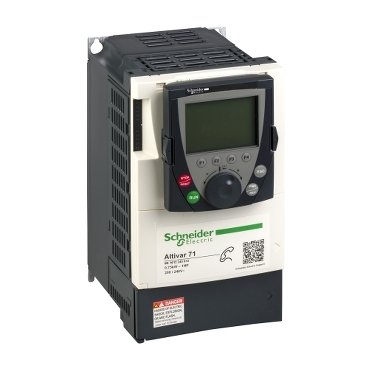
ATV71H075M3 Schneider Electric
Rated 5 out of 5 based on 1 customer rating
$1,908.00 Original price was: $1,908.00.$1,560.00Current price is: $1,560.00.
The atv71h075m3 is a Schneider Electric Drive for industrial automation, available at PLCHMI Shop with fast worldwide shipping and a genuine product guarantee.
1 in stock
Free shipping on orders over $5000!
- Satisfaction Guaranteed
- No Hassle Refunds
- Secure Payments
Category: speed drives
Description
| Range of Product | Altivar 71. |
|---|---|
| Product or Component Type | Variable-speed drive. |
| Product-Specific Application | Complex, high-power machines. |
| component name | ATV71. |
| Motor power (kW) | 0.37 kW, single phase 200–240 V. 0.75 kW, 3 phase 200–240 V. |
| Maximum Horse Power Rating | 1 hp, 3 phase, 200–240 V. 0.5 hp, single phase, 200–240 V. |
| Maximum motor cable length | 164.04 ft (50 m) shielded cable. 328.08 ft (100 m) unshielded cable. |
| power supply voltage | 200…240 V, 15…10 %. |
| Phase | Single phase. 3 phase. |
| Line current | 5.3 A 240 V, 3 phase, 0.75 kW, 1 hp. 5.8 A 240 V, single phase, 0.37 kW / 0.5 hp. 6.1 A 200 V, 3 phase, 0.75 kW, 1 hp. 6.9 A 200 V, single phase, 0.37 kW / 0.5 hp. |
| EMC filter | Integrated. |
| Assembly style | With heat sink. |
| Apparent power | 1.4 kVA 240 V, single phase, 0.37 kW, 0.5 hp. 2.2 kVA 240 V, 3 phase, 0.75 kW, 1 hp. |
| Prospective line Isc | 5 kA, 3 phase. 5 kA, single phase. |
| Nominal output current | 3 A 4 kHz, 230 V, single phase, 0.37 kW / 0.5 hp. 4.8 A 4 kHz, 230 V, 3 phase, 0.75 kW, 1 hp. |
| Maximum transient current | 4.5 A 60 s single phase 0.37 kW / 0.5 hp. 4.9 A 2 s single phase 0.37 kW / 0.5 hp. 7.2 A 60 s 3 phase 0.75 kW / 1 hp. 7.9 A 2 s, 3 phase, 0.75 kW, 1 hp. |
| Output frequency | 0.1…599 Hz. |
| Nominal switching frequency | 4 kHz. |
| Switching frequency | 1…16 kHz adjustable. 4…16 kHz with derating factor. |
| Asynchronous motor control profile | Sensorless flux vector control (SFVC) (voltage or current vector). Voltage/frequency ratio (2 or 5 points). ENA (Energy adaptation) system for unbalanced loads. Flux vector control (FVC) with sensor (current vector). |
| Types of polarization | No impedance Modbus. |
| Product destination | Synchronous motors. Asynchronous motors. |
|---|---|
| power supply voltage limits | 170…264 V. |
| power supply frequency | 50…60 Hz, 5…5 %.. |
| power supply frequency limits | 47.5…63 Hz. |
| Speed range | 1…100 asynchronous motor in open-loop mode, without speed feedback. 1…1000 asynchronous motor in closed-loop mode with encoder feedback. 1…50 synchronous motor in open-loop mode, without speed feedback. |
| Speed accuracy | +/- 0.01 % of nominal speed in closed-loop mode with encoder feedback 0.2 Tn to Tn. +/- 10 % of nominal slip without speed feedback, 0.2 Tn to Tn. |
| Torque accuracy | +/- 15 % in open-loop mode, without speed feedback. +/- 5 % in closed-loop mode with encoder feedback. |
| Transient overtorque | 170 % +/- 10 % 60 seconds every 10 minutes. 220 % +/- 10 % 2 s. |
| Braking torque | <= 150 % with braking or hoist resistor. 30 % without braking resistor. |
| Synchronous motor control profile | Vector control without speed feedback |
| Regulation loop | Adjustable PI regulator. |
| Motor slip compensation | Automatic, whatever the load. Adjustable. Suppressable. Not available in voltage/frequency ratio (2 or 5 points). |
| diagnostic | For drive voltage, 1 LED (red) |
| Output voltage | <= power supply voltage. |
| insulation | Electrical between power and control. |
| type of cable for mounting in an enclosure | With a NEMA Type1 kit, 3 UL 508 cable 104 °F (40 °C), copper 75 °C, / PVC. With an IP21 or an IP31 kit, 3 IEC cable 104 °F (40 °C), copper 70 °C, / PVC. Without mounting kit 1 IEC cable, 113 °F (45 °C), copper, 70 °C, / PVC. Without mounting kit 1 IEC cable 113 °F (45 °C), copper 90 °C, XLPE/EPR. |
| Electrical connection | Terminal 2.5 mm2, AWG 14 AI1-/AI1+, AI2, AO1, R1A, R1B, R1C, R2A, R2B, LI1… LI6, PWR). Terminal 4 mm2, AWG 10 (L1/R, L2/S, L3/T, U/T1, V/T2, W/T3, PC/-, PO, PA/+, PA, PB). |
| Tightening torque | 5.31 lbf.in (0.6 N.m.) (AI1-/AI1+, AI2, AO1, R1A, R1B, R1C, R2A, R2B, LI1… LI6, PWR). 12.39 lbf.in (1.4 N.m.), 12.3 lb.in L1/R, L2/S, L3/T, U/T1, V/T2, W/T3, PC/-, PO, PA/+, PA, PB). |
| Supply | Internal supply for reference potentiometer (1 to 10 kOhm) 10.5 V DC +/- 5 %, <10 mA overload and short-circuit protection. Internal supply (24 V DC, 21…27 V), <200 mA overload and short-circuit protection. |
| analogue input number | 2. |
| Analogue input type | AI1-/Al1+ bipolar differential voltage +/- 10 V DC 24 V max 11 bits + sign. AI2 software-configurable current 0…20 mA, 242 Ohm, 11 bits AI2 software-configurable voltage 0…10 V DC 24 V max 30000 Ohm 11 bits. |
| input sampling time | 2 ms +/- 0.5 ms AI1-/Al1+) – analog. 2 ms +/- 0.5 ms Al2) – analog 2 ms +/- 0.5 ms LI1…LI5) – discrete. 2 ms +/- 0.5 ms (LI6) if configured as logic input, discrete. |
| Response time | <= 100 ms in STO (Safe Torque Off). AO1: 2 ms +/- 0.5 ms analog. R1A, R1B, and R1C: 7 ms +/- 0.5 ms discrete R2A, R2B: 7 ms +/- 0.5 ms discrete. |
| absolute accuracy precision | +/- 0.6 % AI1-/Al1+) for a temperature variation 60 °C. +/- 0.6 % AI2) for a temperature variation 60 °C. +/- 1 % AO1) for a temperature variation 60 °C |
| Linearity error | +/- 0.15 % of maximum value (AI1-/Al1+, AI2) +/- 0.2 % AO1). |
| analogue output number | 1 |
| Analogue output type | AO1 software-configurable logic output 10 V, 20 mA. AO1 software-configurable current 0…20 mA, 500 Ohm, 10 bits. AO1 software-configurable voltage 0…10 V D.C 470 Ohm 10 bits. |
| Discrete output number | 2 |
| Discrete output type | Configurable relay logic (R1A, R1B, R1C): NO/NC: 100000 cycles. Configurable relay logic (R2A, R2B): NO: 100000 cycles |
| Minimum switching current | 3 mA, 24 V DC, configurable relay logic. |
| Maximum switching current | R1, R2 2 A 250 V AC inductive, cos phi = 0.4. R1, R2, 2 A, 30 V DC inductive, cos phi = 0.4. R1, R2 5 A 250 V AC resistive, cos phi = 1. R1, R2 5 A 30 V DC resistive, cos phi = 1 |
| Discrete input number | 7 |
| Discrete input type | LI1…LI5 programmable 24 V DC level 1 PLC 3500 Ohm. LI6 switch-configurable 24 V DC level 1 PLC 3500 Ohm. LI6 switch-configurable PTC probe 0… 1500 Ohm PWR safety input: 24 V DC, 1500 Ohm, ISO 13849-1. level d |
| Discrete input logic | Negative logic (sink) LI1… LI5), > 16 V, < 10 V. Positive logic (source): LI1… LI5,, < 5 V, > 11 V. Negative logic (sink) LI6 if configured as logic input, > 16 V, < 10 V. Positive logic (source) LI6 if configured as logic input, < 5 V, > 11 V. |
| Acceleration and deceleration ramps | Linearly adjustable separately from 0.01 to 9000 s S, U or customized. Automatic adaptation of ramp if braking capacity exceeded by using resistor. |
| Braking to standstill | By DC injection. |
| Protection type | Against exceeding the speed limit. Against input phase loss drive. Break on the control circuit drive. Input phase breaks drive. Line supply overvoltage drive. Line supply undervoltage drive. Overcurrent between output phases and earth drive. Overheating protection drive. Overvoltages on the DC bus drive. Short-circuit between motor phases drive. Thermal protection drive. Motor phase break motor Power removal motor. Thermal protection motor. |
| Insulation resistance | > 1 mOhm, 500 V DC for 1 minute to earth. |
| Frequency resolution | Analog input: 0.024/50 Hz. Display unit: 0.1 Hz |
| communication port protocol | Modbus. CANopen. |
| Connector type | 1 RJ45 on front face)Modbus. 1 RJ45 on terminal)Modbus. Male SUB-D 9 on RJ45CANopen. |
| Physical interface | 2-wire RS 485 Modbus. |
| Transmission frame | RTU Modbus. |
| Transmission rate | 4800 bps, 9600 bps, 19200 bps, 38.4 Kbps Modbus on terminal. 9600 bps, 19200 bps Modbus on front face. 20 kbps, 50 kbps, 125 kbps, 250 kbps, 500 kbps, 1 Mbps CANopen. |
| Data format | 8 bits, 1 stop, even parity Modbus on front face. 8 bits, odd even or no configurable parity Modbus on terminal. |
| Number of addresses | 1…127 CANopen. 1…247 Modbus |
| Method of access | Slave CANopen. |
| Marking | CE |
| Operating position | Vertical +/- 10 degrees. |
| Height | 9.06 in. (230 mm). |
| Depth | 6.89 in (175 mm). |
| Width | 5.12 in. (130 mm). |
| Net Weight | 6.61 lb (US) (3 kg). |
| Functionality | Full |
| Specific application | Other applications. |
| Option card | Communication card: CC-Link. Controller inside programmable card. Communication card: DeviceNet. Communication card: EtherNet/IP. Communication card: Fipio. I/O extension card. Communication card Interbus-S. Interface card for encoder. Communication card: Modbus Plus. Communication card: Modbus TCP. Communication card: Modbus/Uni-Telway. Overhead crane card. Communication card, Profibus DP. Communication card Profibus DP V1. |
| Noise level | 43 dB 86/188/EEC. |
|---|---|
| Dielectric strength | 2830 V DC between earth and power terminals. 4230 V DC between control and power terminals. |
| Electromagnetic compatibility | 1.2/50 µs–8/20 µs surge immunity test level 3 IEC 61000-4-5. Conducted radio-frequency immunity test level 3 (IEC 61000-4-6). Electrical fast transient/burst immunity test level 4 (IEC 61000-4-4). Electrostatic discharge immunity test level 3 (IEC 61000-4-2).. Radiated radio-frequency electromagnetic field immunity test level 3 (IEC 61000-4-3). Voltage dips and interruptions immunity test (IEC 61000-4-11). |
| Standards | IEC 60721-3-3 class 3S2. EN/IEC 61800-5-1. UL Type 1. EN 61800-3 Environments, Category C2. IEC 60721-3-3 class 3C1. EN 61800-3 environments 2 category C2. EN/IEC 61800-3. EN 55011, class A, group 1 |
| Product Certifications | CSA. UL. C-tick. NOM 117. GOST. |
| Pollution degree | 2 EN/IEC 61800-5-1 |
| IP degree of protection | IP20. |
| Vibration resistance | 1 gn (13…200 Hz) EN/IEC 60068-2-6 1.5 mm peak to peak 3…13 Hz) EN/IEC 60068-2-6. |
| Shock resistance | 15 gn 11 ms EN/IEC 60068-2-27. |
| Relative humidity | 5…95 % without condensation IEC 60068-2-3. 5… 95%% without dripping water IEC 60068-2-3. |
| Ambient air temperature for operation | 14…122 °F (-10…50 °C) without derating. |
| Ambient Air Temperature for Storage | -13…158 °F (-25…70 °C). |
| Operating altitude | <= 3280.84 ft (1000 m) without derating 3280.84…9842.52 ft (1000…3000 m) with current derating 1 % per 100 m. |
| Category | 22130-ATV71: 1/2 THRU 5HP DRIVES. |
|---|---|
| Discount Schedule | CP4C |
| GTIN | 3389118064218. |
| Returnability | No |
| Country of origin | ID |
| Unit Type of Package 1 | PCE. |
|---|---|
| Number of Units in Package 1 | 1. |
| Package 1: Height | 9.25 in (23.5 cm). |
| Package 1: Width | 9.65 in (24.5 cm). |
| Package 1 Length | 12.01 in (30.5 cm). |
| Package 1: Weight | 9.26 lb (US) (4.2 kg). |
Related products
-
Sale!

VW3A3316 Schneider Electric
Rated 5 out of 5$845.00Original price was: $845.00.$650.00Current price is: $650.00. -
Sale!
ATV32H018M2 Schneider Electric
Rated 5 out of 5$627.00Original price was: $627.00.$482.00Current price is: $482.00.
