Exploring Reliable Methods for Managing Electrical Signals in Control Systems
Every industrial control system depends on accurate, reliable signal transmission between field devices and the controller. A temperature transmitter, pressure sensor, or limit switch is only useful if its signal reaches the PLC or DCS intact — free from noise, drift, or interference. Managing these signals correctly is one of the most underappreciated aspects of control system design, and getting it wrong leads to erratic process behavior that can be difficult to diagnose.
Analog vs. Digital Signals in Control Systems
Digital (discrete) signals represent simple on/off states — a limit switch, a proximity sensor, a relay contact. Analog signals represent a continuous range of values — typically 4–20mA current loops or 0–10V voltage signals — used for readings like flow rate, level, or pressure.
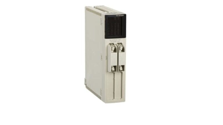
Each signal type requires appropriate hardware. Discrete field devices connect to digital I/O modules, while analog instruments require analog input modules such as the 140ACI03000 or the TM3AI4 analog input module, which are designed to accurately interpret current or voltage signals across their full working range.
Why 4–20mA Current Loops Remain the Industry Standard
Current loop signals are widely used in industrial settings because current, unlike voltage, doesn’t degrade over long wire runs the way voltage signals do. A 4–20mA signal also has a built-in diagnostic advantage: a reading of exactly 0mA typically indicates a broken wire or failed transmitter, rather than a legitimate process value, making wiring faults easier to detect.
Signal Isolation for Noisy Environments
In environments with variable frequency drives, large motors, or high-voltage switching nearby, electrical noise can couple into signal wiring and cause erratic readings. Signal isolators and conditioners, such as the Pepperl+Fuchs KFD2-SR2-2.2S isolator, break galvanic connections between field wiring and control system electronics, protecting sensitive I/O modules from noise, ground loops, and voltage transients while maintaining accurate signal transfer.
Proper Wiring Practices Reduce Signal Errors
Beyond hardware selection, physical wiring practices significantly affect signal reliability:
- Route signal cables separately from power cables, maintaining adequate separation distance
- Use shielded, twisted-pair cable for analog signals, grounding the shield at one end only
- Avoid running signal wiring parallel to VFD output cables, which carry significant electrical noise
- Terminate cable shields properly to avoid creating unintended ground loops
Module Selection Based on Signal Type and Range
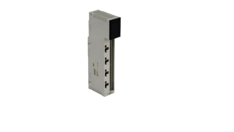
Not all analog modules support the same signal ranges or resolution. Selecting a module rated for the specific signal type — whether that’s a standard 4–20mA loop, a 0–10V range, or a thermocouple/RTD input — ensures the controller reads accurate values without requiring additional signal conversion hardware. Modules like the BMXEAE0300 are built for specific analog input configurations and should be matched to the instrument’s actual output characteristics.
Redundancy for Critical Signals
For safety-critical or high-value process signals, some facilities implement redundant transmitters or dual signal paths so a single wiring fault or transmitter failure doesn’t blind the control system to a critical process variable. This is particularly relevant in the context of PLCs used in process control and safety systems.
Frequently Asked Questions
Q: Why is 4–20mA preferred over 0–10V for long cable runs? A: Current signals don’t degrade over distance or resistance the way voltage signals do, making 4–20mA more reliable for long wire runs common in industrial facilities.
Q: What causes analog signal drift in control systems? A: Common causes include electrical noise from nearby VFDs or motors, poor shield grounding, transmitter calibration drift, and inadequate signal isolation.
Q: Do all analog input modules require signal isolation? A: Not always — it depends on the electrical environment. Facilities with significant electrical noise from drives or switching equipment benefit most from isolated signal conditioning.
Q: How can I tell if a 4–20mA signal fault is a wiring problem or a transmitter failure? A: A reading of exactly 0mA typically points to a broken wire or power loss, while an unusually stuck or erratic reading with continuity intact often points to a transmitter or module fault.